Verification of buckling resistance of built-up cross-sections
The buckling resistance perpendicular to the strong axis is given by expression
![]()
Where is: | χ |
|
A |
| |
fy |
| |
γM1 |
|
The effective cross-sectional area is considered for class 4.
The slenderness λy in the direction perpendicular to the strong axis y is given by formula
![]()
Where is: | Lcr,y |
|
iy |
|
The relative slenderness ![]() is given by the expression
is given by the expression
![]()
Where is: | λy |
|
λ1 |
| |
Aeff |
| |
A |
|
The slenderness value λ1 is given by the formula

Where is: | E |
|
fy |
|
The value of the imperfection factor α is set according to the buckling curves a, b, c, d. The factor χy corresponds to the relative slenderness ![]() and is calculated using expression
and is calculated using expression

however, following condition has to be fulfilled
![]()
where
![]()
The partial cross-section fails if the specified axial force is greater than the resistance Nb,Rd,y.
The calculation of buckling resistance perpendicular to the weak axis follows. The elastic flexural buckling force Ncr is given by the expression
![]()
Where is: | lcr,z |
|
kE,θ |
| |
E |
| |
Ieff |
|
Following formula is used for Ieff for lacing
![]()
Where is: | h0 |
|
A |
|
The second moment of area I1 is calculated for built-up cross-sections with battens using the expression
![]()
Where is: | A |
|
h0 |
| |
Iz |
|
The radius of gyration i0 is given by the expression
![]()
For the slenderness
![]()
the factor μ is selected. The effective value of the moment of inertia Ieff is given by the expression
![]()
The partial cross-section fails if the specified axial force is greater than the resistance Ncr.
The verification of the shear stiffness SV follows. The shear stiffness is given by the follwoing formula for battens
![]()
or
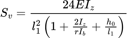
However, following expression has to be fulfilled
![]()
Where is: | l1 |
|
r |
| |
Ib |
| |
h0 |
|
The axial force shouldn't exceed the shear stiffness SV. Also following expression has to be fulfilled
![]()
The force in the middle of the batten is calculated using formula
![]()
The force in lacing is
![]()
Where the moment MS is given by the expression
![]()
Where is: | e0 |
|
The buckling resistance is given by expression
![]()
Where is: | χy |
|
A |
| |
fy |
| |
γM1 |
|
where the factor χz corresponds to the slenderness λ, that is given by the expression
![]()
Where is: | l1 |
|
imin |
|
The relative slenderness ![]() is given by the formula
is given by the formula
![]()
where

The value of the imperfection factor α is set according to the buckling curves a, b, c, d. The factor χz corresponds to the relative slenderness ![]() and is calculated using expression
and is calculated using expression

however, following condition has to be fulfilled
![]()
where
![]()
where

The shear force VS is calculated for the batten
![]()
Where the moment MS is given by the expression
![]()
Where is: | l1 |
|
Vy |
|
The bending resistance of partial cross-section for bending moment My is calculated for the classes 1 and 2 according to the following formula:
![]()
The formula for the class 3:
![]()
The formula for the class 4:
![]()
Where is: | Wpl,y |
|
Wy |
| |
Wy,eff |
|
The bending resistance of partial cross-section for bending moment Mz is calculated for the classes 1 and 2 according to the following formula:
![]()
The formula for the class 3:
![]()
The formula for the class 4:
![]()
Where is: | Wpl,z |
|
Wz |
| |
Wz,eff |
|
The verification is done for two points: the mid point of the distance between two battens and in the connection of batten.
The verification in the mid point of the distance between two battens:
![]()
Where is: | n |
|
dN |
| |
ky |
|
The verification in the connection of batten:
![]()