RC column
Introduction
This tutorial shows a design of RC column of a hexagonal cross-section. With 200mm depth of the section and 2000mm length, the column is subjected to axial compressive force and biaxial bending. The actions in the ultimate limit state are: Nx= 400kN, My= 2.33kNm and Mz= 5.46kNm. The stress limitation (serviceability limit state) should be checked for Nx= 350kN and My= 2.00kNm. The strength class of the concrete is C30/37 X0 and steel grade B500 is used for reinforcement.
Starting a new project
The following screen appears after running program "Concrete":
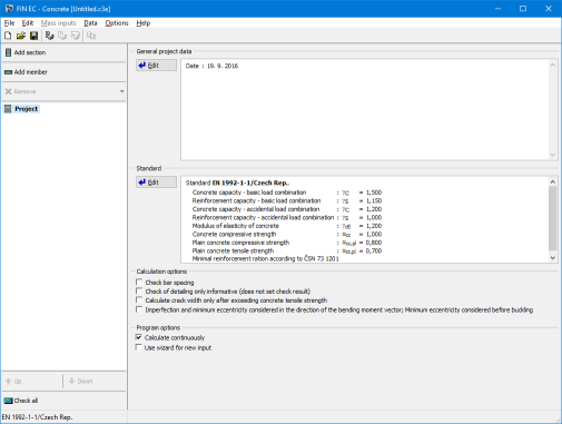 The start screen of the "Concrete" program
The program provides opportunity to calculate a unlimited number of partial tasks per project. There are two task types supported by the software: "Section" and "Member". The type "Section" is suitable for easy verification of RC cross- sections, the type "Member" is usually used for a verification of the structures, which were created in the programs "Fin 2D" and "Fin 3D". We will use the type "Section" for our analysis. The start screen contains a part "General project data", where the job name, description and other project identification data can be entered. After clicking the "Edit" button, we first enter the job name and other project details:
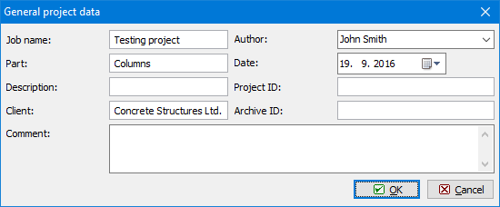 "General project data" dialog box
These data can be displayed in the header or footer of the final documentation.
Prior to commencing any work, it is advisable to save the job. This can be done either using "![]() " button, or in the main menu clicking on "File" – "Save As", or using the "Ctrl+S" shortcut.
" button, or in the main menu clicking on "File" – "Save As", or using the "Ctrl+S" shortcut.
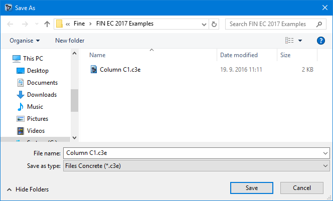 Saving the project
Now we can proceed to entering a new task by clicking the "Add Section" button in the upper part of the program’s tree menu.
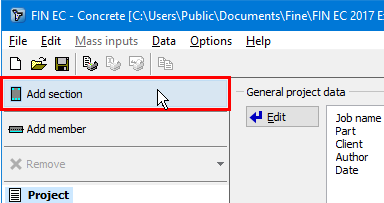 Adding a new section
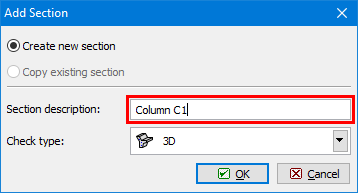
The following dialog box appears, in which we can enter the section’s name ("Column") into the "Section description" field, confirming by clicking the "OK" button.
 Dialog box for adding a new section
A new item has been generated in the tree menu, representing the new added section ("Column C1"). The program has now automatically selected this item; therefore we can directly proceed to entering the section parameters.
 Main screen for "Section" task type
Section, Material, Reinforcement
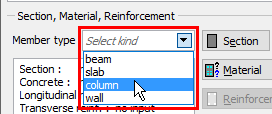
At first it is necessary to enter the basic geometrical and material characteristics of the section in the "Section, Material, Reinforcement" frame. We select the function of the member in the structure from the "Member type" drop-down list. Available types are "beam", "slab", "column" or "wall".
 Choice of member type
In our example we select member type "column". This selection affects the analysis and verifications of the reinforcement arrangement.
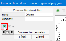
As a hexagon is not included in the library of pre-defined cross-sections, we need to use the "![]() " button to define geometry of a general polygon. The polygon shape can be defined graphically or numerically in the window "Cross-section editor". The shape of cross-section is defined by six points, which have to be defined in the correct order. We can define each of the points numerically by clicking the "+" button, located in the bar in the left upper corner above the table of points.
" button to define geometry of a general polygon. The polygon shape can be defined graphically or numerically in the window "Cross-section editor". The shape of cross-section is defined by six points, which have to be defined in the correct order. We can define each of the points numerically by clicking the "+" button, located in the bar in the left upper corner above the table of points.
 Button for input of points
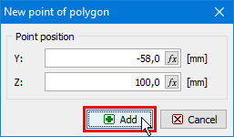
A new window with input lines for enetring coordinates appears. We specify the coordinates of the forst point [-0,058;0,100] and insert the point by the button "Add".
 Input of particular points of the polygon
We will specify positions of following points [-0,058;0,100], [0,058;0,100], [0,115;0,000], [0,058;-0,100], [-0,058;-0,100], [-0,115;0,000] in the same way. After entering coordinates of the last point, we return to the "Cross-section editor" dialog box by clicking the "Cancel" button.
The geometry of the cross-section appears on the right side of the dialog box; we can change the points coordinates either directly in the table on the left side or graphically on the right side. We close the dialog box by clicking the "OK" button.
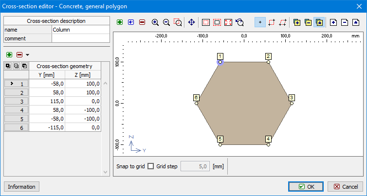 Geometry of the polygon
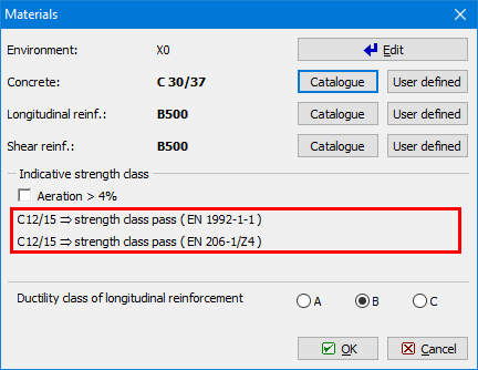
We proceed with defining the material properties in "Materials" dialog box which is run by clicking the "Material" button in the "Section, Materials, Reinforcement" fram. Assuming the column is located inside of the structure we select "X0" for "Exposure class", as the column is not in contact with outside environment. Subsequently we define the material properties of concrete and longitudinal and transversal reinforcement. We can select standardized materials from the library of pre-defined materials clicking the "Catalogue" button at relevant lines.
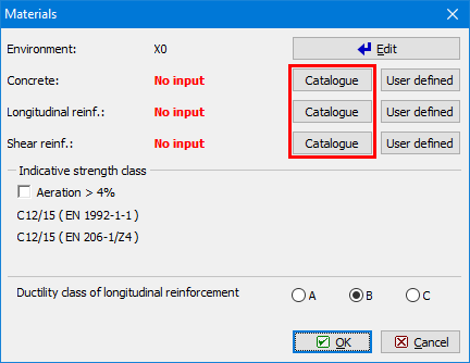 Window "Materials"
For concrete we select the strength class "C30/37" and close the dialog box by clicking "OK".
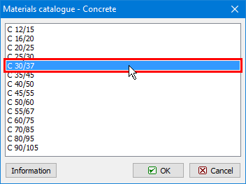 Choice of strength class for concrete
Proceeding to definition of the steel properties, we select the grade "B500" for both longitudinal and transversal reinforcement and close the dialog box by clicking "OK".
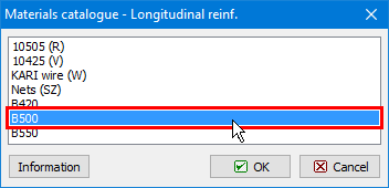 Steel grade selection
After returning to the "Materials" dialog box we can check the summary of the selected materials and confirm whether the selected class of concrete fulfils requirements on the "Indicative strength class" given by the selected exposure class. We exit the window "Materials" by clicking "OK".
 Indicative strength class check in "Materials" window
Loads
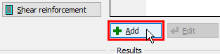
After defining the geometry of the section and material properties, we can proceed either with defining the reinforcement or loads. In our example we first define a load case because then we are able to check the results of the reinforcement assessment during its definition. To create a load case, we click the "Add" button located under the "Loads" table.
 Button for insertion of new loads
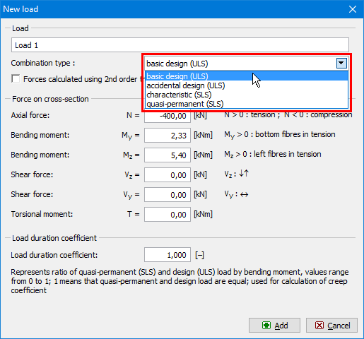
In the "New load" window we select a "Combination type". This type should be selected according to the type of combination, which was used for determination of forces and moments. This input affects the type of verification. The following options are available:
Basic design (ULS) |
|
Accidental design (ULS) |
|
Characteristic (SLS) |
|
Quasi-permanent (SLS) |
|
Subsequently we enter the forces and bending moments acting on the cross-section; in our example the axial force is N= -400kN (negative value denotes compression) and the bending moments are My= 2,33kNm and Mz= 5,46kNm.
Also, we should enter the "Load duration coefficient", i.e. the ratio of quasi-permanent and total loads for calculation of the creep coefficient. If the exact value is not available, we can leave the conservative value of 1.00, which means that the total load is considered quasi-permanent in the calculations. The new load is confirmed by clicking the "Add" button and "Cancel" to exit the dialog box.
 Input of new load
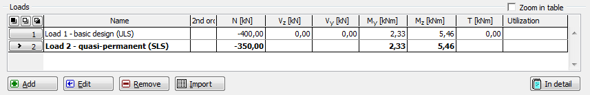
To define the loads for the serviceability limit state, analogical procedure is used as for the ultimate limit state loads. To assess the stress limitation, we select "Combination type – characteristic (SLS)" and enter the relevant axial compressive force N= -350kN and the bending moment My= 2.00kNm. After input confirmation by the button "Add", we will exit the window by using the button "Cancel".
As result, a table summarizing all defined load cases is generated in the dialog box.
 Loads
Loads
The number of loads is not limited in the software. The input can be done also in a batch using text or *.csv file (button "Import").
Reinforcement
After returning to the main dialog box, we can proceed to defining the longitudinal and transverse reinforcement. We open the dialog box "Edit reinforcement sector" for longitudinal reinforcement definition by clicking on the "Reinforcement" button in the "Section, Material, Reinforcement" frame. The upper part of the window contains an option to select a calculation method of the cover. We keep the method ""
In this dialog box, we can define the reinforcement either numerically in the table on the left-hand side or graphically in the right part of the dialog box.We can also take advantage of a simplified approach by clicking "![]() " and then the "Generate" button in the left lower corner of the dialog box. In our example we will use this option.
" and then the "Generate" button in the left lower corner of the dialog box. In our example we will use this option.
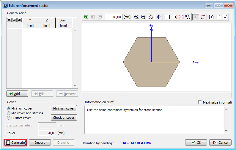 Simplified definition of reinforcement
We can now easily define required longitudinal reinforcement using 16mm bars in each corner of the cross-section, entering 3 layers with appropriate covers:
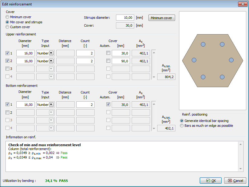 Definition of reinforcement
After defining reinforcement we can immediately check in the lower part of the dialog box that the area of the reinforcement is sufficient and passes design criteria with 34.1% utilization by bending. In the section "Information on reinforcement" we can also confirm that the detailing requirements given by the code are satisfied. Finally we need to check if the covers are correctly defined. Having a column with stirrups, the option "Min cover and stirrups" is selected in the "Cover" section of the dialog box. The program will calculate the minimum required cover of the longitudinal reinforcement as sum of the minimum cover given by the code and the diameter of the stirrups. The calculation can be checked in the dialog box opened by clicking "Minimum cover" button:
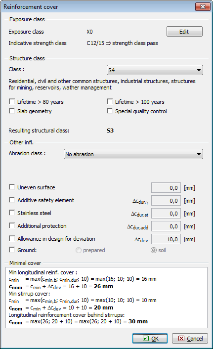 Minimum cover calculation
As it is not necessary to change the settings of cover calculation, we can exit the dialog box by clicking "OK" and return to the dialog box for longitudinal reinforcement definition. To check whether the geometry of the longitudinal reinforcement satisfies requirements on minimum covers, we can run the assessment by clicking "Check of cover".
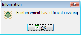 Covers check result
The check returned a positive result, therefore we can return to the main dialog box by clicking "OK".
Shear reinforcement
We can proceed to defining the shear reinforcement by clicking the eponymous button in the main screen.
We specify 10mm diameter boundary stirrups with 150mm spacing:
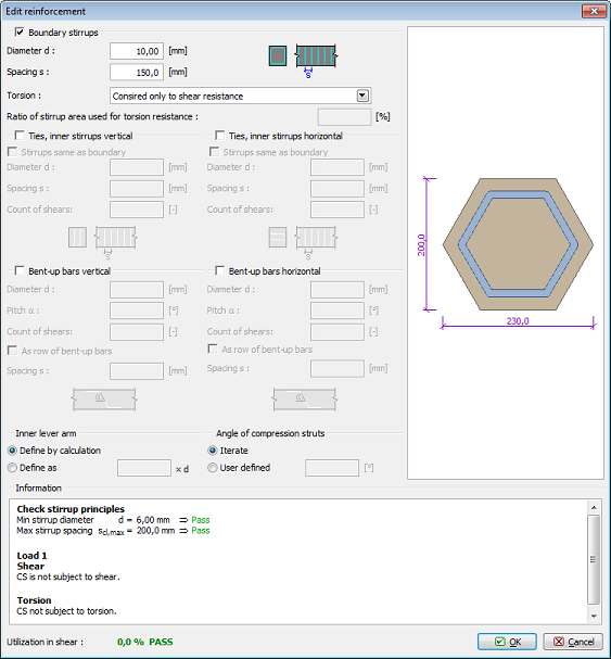 Shear reinforcement definition
Buckling
The next step is defining the buckling parameters. Firstly we need to tick "Calculate buck. Y/Z" boxes followed by entering the nominal lengths of the column for both directions, based on which the effective buckling lengths will be calculated. For a column simply supported on both ends, the effective buckling lengths equal to the nominal. Defining different boundary conditions can be done by clicking the "![]() " buttons for each direction.
" buttons for each direction.
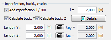 Defined buckling parameters
After defining the buckling parameters, two distinct areas of capacity are shown in the interaction diagram: thin dashed line denotes capacity of the member without influence of buckling and thick line denotes the capacity reduced by buckling effect. To check position of a defined load case in the "Interaction diagram" we need to enter the relevant axial force level; in our example N= -400kN. Program will create a cut through the interaction diagram on this level showing the position of the defined load case:
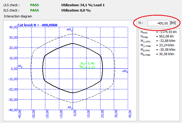 Defining a cut through the interaction diagram
Because we completed definition of all parameters, it is recommended to save the job by clicking "![]() " on the toolbar or using shortcut "Ctrl+S". The actual state of the job during work may not be identical to the one saved on disk; this is indicated by "*" in the program window header. In such case it is advisable to save the job.
" on the toolbar or using shortcut "Ctrl+S". The actual state of the job during work may not be identical to the one saved on disk; this is indicated by "*" in the program window header. In such case it is advisable to save the job.
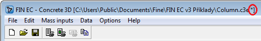 Indication of non-saved job state
Indication of non-saved job stateAs all structural requirements have been checked and satisfied during the definition of parameters and as the main dialog box indicates that the section passes design checks in both ultimate and serviceability limit states, the job can be considered finished.
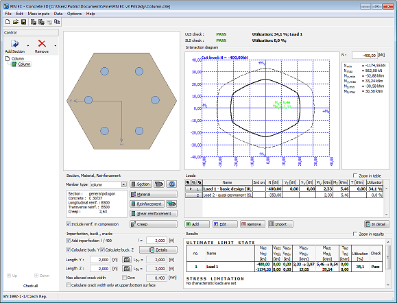 Assessed section in Concrete 3D program
Outputs
When the job is finished and saved, we can proceed to composing the output documentation. First we print out a concise single page output which summarizes all input data and design checks results. Composition of this output is run by clicking "File" and "Graphic output" or "![]() " in the toolbar.
" in the toolbar.
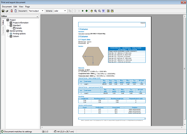 Graphical output of Concrete 3D program
We can print the document directly by clicking "![]() " button or save it on disk as *.pdf or *.rtf file by clicking "
" button or save it on disk as *.pdf or *.rtf file by clicking "![]() " button. We use the second option and save the file on disk. In the dialog box "Save as" we can enter the file name and select the destination folder.
" button. We use the second option and save the file on disk. In the dialog box "Save as" we can enter the file name and select the destination folder.
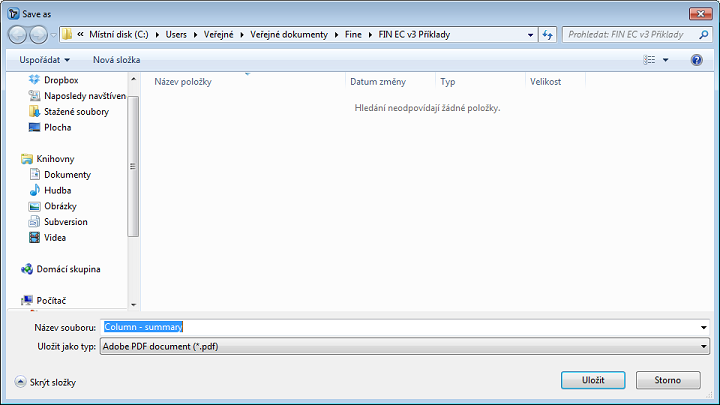 Saving file in *.pdf format
Apart from this concise document, we can also compose a detail text output by clicking the "![]() " button in the toolbar or selecting "File" and "Text/Graphic output" in the main menu. However, as we are still in the print and export document dialog box we can change the document type to text output directly in the toolbar’s "Document" drop-down list.
" button in the toolbar or selecting "File" and "Text/Graphic output" in the main menu. However, as we are still in the print and export document dialog box we can change the document type to text output directly in the toolbar’s "Document" drop-down list.
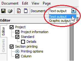 Change of output type
After switching to the "Text output" mode we can set in the "Editor" which parts of the assessment will be included in the output and how detailed the output shall be.
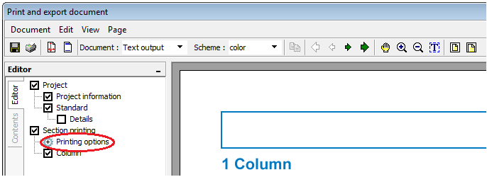 Printing options of text outputs
Program will immediately re-generate the output to reflect each change made in the settings in the tree on the left-hand side. Once the output contains all required information, we can again save the document on disk.
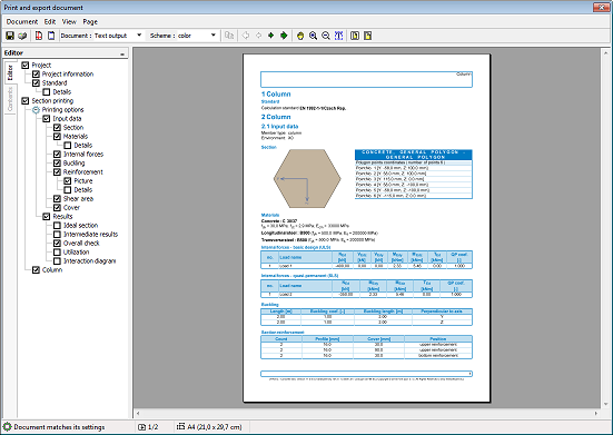 Generated text output
Completing the outputs generation, our work is done.