Bolts
Spacings
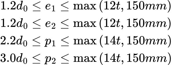
Following values are given in the standard as minimum and maximum spacings for bolts in shear:
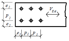 Spacing
Where is: | t |
|
d0 |
| |
e1, e2, p1, p2 |
|
Following values are recommended:
Bolts | Recommended spacing (mm) | ||
p; p2 | e | e | |
M12 | 44 | 30 | 25 |
M16 | 55 | 40 | 30 |
M20 | 70 | 50 | 40 |
M24 | 80 | 60 | 50 |
M27 | 90 | 70 | 55 |
M30 | 100 | 75 | 60 |
M36 | 120 | 90 | 70 |
Shear resistance
The design value of shear resistance of n bolts in unthreaded portion is given by the expression:
![]()
The resistance in threaded portion is calculated for bolt materials 4.6, 5.6, 8.8 using expression
![]()
and for material 4.8, 5.8, 10.9 with the help of this formula:
![]()
Where is: | Fv.Rd |
|
fub |
| |
As |
|
The program calculates only the shear resistance in threaded portion of the bolt. The shear resistance of the unthreaded portion is not considered in the analysis
Bearing resistance
The bearing resistance in vertical direction is calculated for the minimum of coefficient α
![]()
and for minimum value of k1
![]()
For the horizontal direction, the minimum value of α is selected from these formulas
![]()
the minimum value of k1 is selected from following expressions for horizontal direction
![]()
The resistance is given by the formula
![]()
Where is: | Fb.Rd |
|
d0 |
| |
e1, e2, p1, p2 |
| |
d |
| |
t |
|
Slip resistance
The preloading force is calculated using the expression (3.7):
![]()
The design value of slip resistance is given by the formula (3.6)
![]()
The connections may be preloaded only in serviceability limit state. In that cases, shear and bearing resistance of bolts are verified for ultimate limit state. The software considers the preloading in the ultimate limit state. In such cases, only bearing resistance is checked.
Following values of slip factor μ are used in the software (based on the table 3.7):
Class | Description | μ |
A | Blasted with shot or grit | 0.5 |
B | Blasted with shot or grit (spray-metallised with aluminium or zinc based product or with alkali-zinc silicate paint with a given thickness) | 0.4 |
C | Cleaned by wire brush or flame cleaning | 0.3 |
D | Without any treatment | 0.2 |
Long joints
The shear resistance Fv.Rd in long joints, where the distance between the centres of the end fasteners is more than 15d, is reduced with the help of the coefficient
![]()
Where Lj is the distance between the centres of the end fasteners.
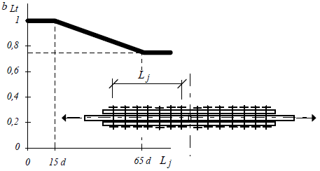 The resistance reduction for long joints
The design resistance of single lap joint with only one bolt row is limited according the chapter 3.6.1(10) using expression
![]()
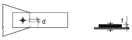 Single lap joint with only one bolt row
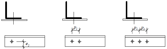
Angles connected by one leg
The resistance of single angle in tension, that is connected by a row of bolts in one leg, is calculated in accordance with the chapter 3.10.3 using the following expressions
joints with one bolt
![]()
joints with 2 bolts
![]()
joints with 3 or more bolts
![]()
Where is: | γM2 |
|
Anet |
| |
β2, β3 |
|
The values of reduction factors β2, β3 are based on the table 3.8 of EN 1993-1-8:
Pitch | ≤2,5d0 | ≥2,5d0 |
Two bolts | 0,4 | 0,7 |
Three bolts and more | 0,5 | 0,7 |
 The resistance reduction of unsymmetrical angle
All angles in the software are analysed as unsymmetrical.