Program Steel Connections
The software "Steel connections" verifies steel connections according to EN 1993-1-8.
User interface
The user interface consists of a main menu with toolbars in the upper part of the window, tree menu on the left and input/display part on the right side of the window. The main menu contains all tools and functions, which can be used during the work. The tree menu is used for the administration of individual project tasks as well as for switching between parts of an input. The work with the tree menu is described in the chapter "Tree menu". The tree menu can be alternated by the part "Entry" of the main menu. Tools for documents printing are organized in the window "Print and export document", which can be opened using the printing icon in the toolbar "Files" or using the appropriate link in the part "File" of the main menu.
Following particular tasks ("Joints") can be verified in the software:
Beams connection to column |
|
Splice joint of beam |
|
Beam connection to girder |
|
Truss joint |
|
Column base |
|
These tasks can be added with the help of the button "Add" in the heading of the tree menu.
Main screen
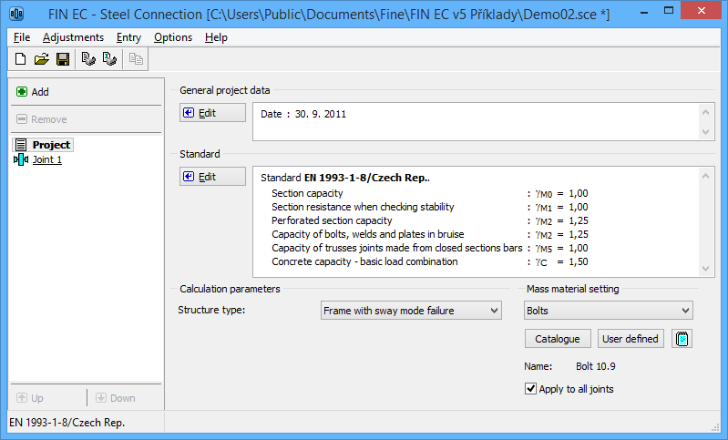
Basic screen of the software contains general data of the project (identification details, design standard).
The frame "General project data" shows data, that can be input in the window "General project data". The window can be opened by using the button "Edit". The entered data can be used in heading and footing of documents.
The design standard including national annex can be changed in the part "Standard". These settings are placed in the window "Standard selection", that can be launched by the button "Edit".
Calculation parameters
This frame contains the choice of structure type. Available are two options:
- Frame with sway mode failure - frames with significant horizontal displacements
- Frame with no sway mode failure - frames where the bracing system reduces significantly the horizontal displacements
This parameter is used in the classification of joints.
Global material input
This part can be used for the input of identical material for all tasks in the project. For such input, it is necessary to select appropriate group (bolts, structural elements etc.), check the setting "Apply to all joints" and select the material from pre-defined database (button "Catalogue") or specify the material numerically (button "User defined").
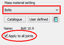 Bolt material for all joints
The appearance of the workspace may be modified in the window "Global settings", that can be opened from the main menu.
 Main application window