Punching
Task
In this example, the task is to design reinforcement against punching of a corner column of 200 x 200 mm square cross-section through a 200 mm thick reinforced concrete slab. The column is located 500 mm from the edges of the slab, which is weakened by an opening of 150 x 500 mm located as per the following sketch. Concrete strength class C25/30 is used in the design.
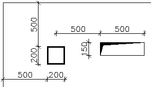 Problem’s geometry
Project data
In the main program window, all essential project data can be entered in the frame in the bottom part. Definition modes can be switched between using the tree on the left hand side; the rest of the window serves as a model space.
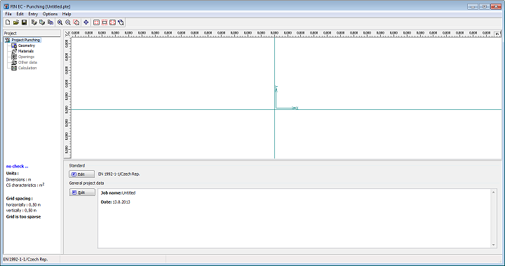 Main window of the program "Punching"
First we enter the company data which will be later used when composing the output documentation. The dialog box "About the company" can be run from the main menu selecting "Settings". In the first tab for instance, we can enter company’s name and address.
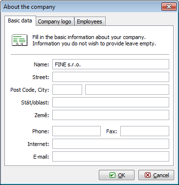 Essential company data in the "About the company" dialog box
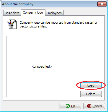
In the second tab we can enter the company’s logo which can later be displayed in the header of the output documentation. The logo can be loaded as an image of any usual format such as *.bmp, *.jpg, *.ico etc. To import the logo we run the dialog box by clicking "Load".
 Button for loading the logo file
For selecting files, the standard Windows user interface is used. After opening the folder containing the file, we load the file by clicking the "Open" button.
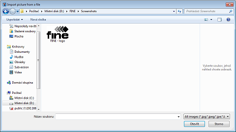 Logo file selection
A preview of the logo is subsequently displayed; its size will be automatically adjusted to the graphic layout of the program’s output.
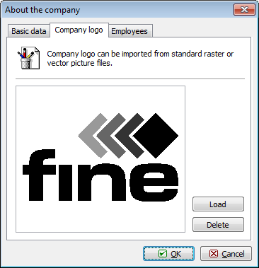 A logo loaded to the program
In the last tab "Employees", we can enter a list of company’s employees from which we can select the author of the project. New employees are entered by clicking the "Add" button.
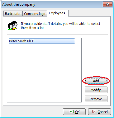 Entering a list of employees
We exit the dialog box "About the company" by clicking "OK". The company’s data are shared with all EC programs and can be therefore used in other programs of the package.
Basic settings
After entering data in the "About the company" dialog box we return to the main screen. Here we can enter essential information about the job in the "General project data" dialog box which opens by clicking the "Edit" button.
 Opening "General project data" dialog box from the main window
In the "General project data" dialog box we can enter e.g. job’s name, description, remarks etc. It is also possible to select the author of the project from the list of the employees which we created in the "About the company" dialog box. All this information can be later displayed in the headers or footers of the output documents.
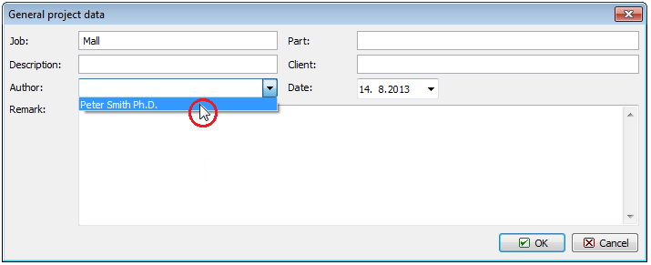 Selecting job’s author from list in "General project data" dialog box
Once we have finished entering the project data, we exit the dialog box by clicking "OK". Then we can proceed to the next step by clicking the "Geometry" button in the tree on the left-hand side.
Geometry
In this dialog box, we first select the column’s cross-section. Clicking the "![]() " button we open the catalogue of pre-defined shapes. Then we select a rectangle and enter the dimensions.
" button we open the catalogue of pre-defined shapes. Then we select a rectangle and enter the dimensions.
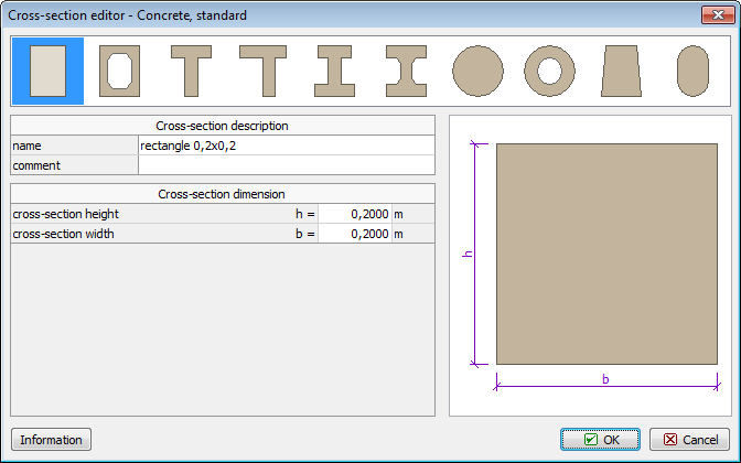 Catalogue of pre-defined cross-section shapes
In the "Geometry" section of the main screen we enter the slab thickness, select the "corner" column type and define the edge distances. The structural layout instantly appears in the model space.
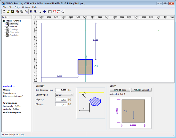 Defining job’s geometry
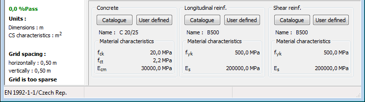
Materials
Proceeding to the next item of the tree - "Materials", another sub-window appears in the main window’s bottom part. In this section we need to specify materials for concrete and slab’s longitudinal and punching shear reinforcement. As we are using a standard concrete class, we click on the "Catalogue" button and open the list of available concrete strength classes. We select C20/25 and exit the dialog box by clicking "OK".
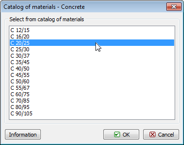 Concrete strength class selection
We proceed analogically to specifying reinforcement material. For both longitudinal and shear reinforcement we will select the "B500" grade.
 Materials’ definition sub-window
Openings
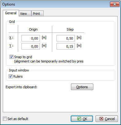
To simplify definition of the opening we first open the "Options" dialog box by selecting "Settings" in the main menu. In the tab "General" we adjust the grid to suit our needs by defining the step as 0.5 m in the X direction and 0.15 m in the Y direction. We exit the dialog box by clicking "OK".
 Adjusting grid step in the "Options" dialog box
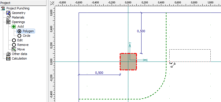
Now we can switch in the tree to "Openings" and "Polygon" and draw the contour of the opening directly in the model space clicking in each of its four corners. To finalize the contour we click again on the first corner.
 Definition of opening in model space
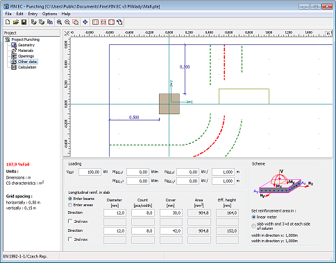
Other data
In this section of the tree we define the loading and longitudinal reinforcement of the slab as VEd = 100 kN and 8 of 12 mm diameter bars per meter run.
 Slab loading and reinforcement definition
Calculation
Switching to the last item of the control tree "Calculation" we can proceed to carrying out the design checks of the punching shear reinforcement. First we need to select the shear reinforcement type; in our example we will use "concentrated stirrups". Then we can either define the reinforcement manually in the table in the definition frame or we can let the program design the reinforcement automatically. Choosing the latter, we run the automatic reinforcement design by clicking the "Design" button.
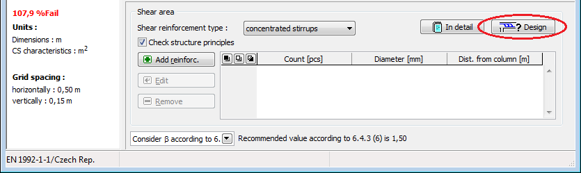 Button for automatic design of punching reinforcement
In the "Reinforcement generation" dialog box we can define invariable reinforcement parameters; other parameters will be defined automatically. Ticking the "Use row spacing" box and entering a value we define fixed stirrup spacing 100 mm; the position of the first row and the stirrups diameters we leave to be designed automatically.
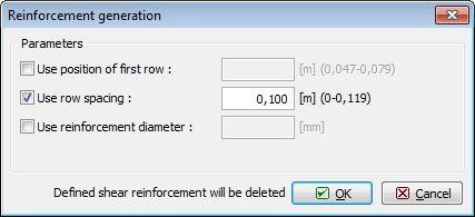 Dialog box for automatic design of reinforcement
After closing the dialog box by clicking "OK" the reinforcement is designed to reach required capacity and fulfil all detailing requirements.
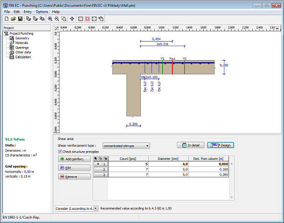 Designed and checked punching shear reinforcement
Finally, we save the job using e.g. the "Ctrl+S" shortcut. The program runs the standard "Save as" dialog box where we find and select the destination folder, enter the name and save the job.
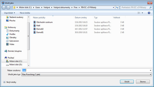 "Save as" dialog box.
Outputs
Composition of the output documentation follows the same procedure as for the other FIN EC programs. We can compose both graphical and/or text output; for the text output we can select in the control tree which chapters of the documentation are to be printed out. We can print the composed document directly by clicking the "![]() " button or save it as a *.pdf or a *.rtf file by clicking the "
" button or save it as a *.pdf or a *.rtf file by clicking the "![]() " button.
" button.
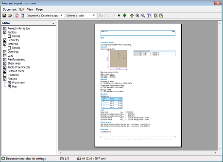 Output documentation composition window
At the beginning we imported the company’s logo into the program, now we can switch on displaying the logo in the documents header in the "Header and footer" dialog box. We run this dialog box by selecting it in the "Document" section of the main menu or directly by clicking the "![]() " button in the toolbar.
" button in the toolbar.
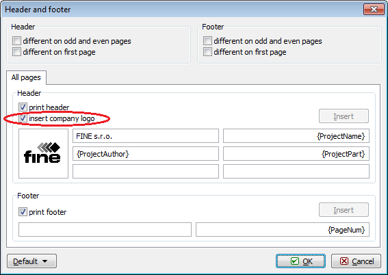 Displaying logo in document’s header
After ticking the "insert company logo" box, the logo appears in the headers of all documents.
 Header with the company’s logo