Calculation of the effective cross-section of trapezoidal sheets
At each calculated cross-section loaded by a combination of normal force N and bending moment My, two effective cross-sections are determined:
- the effective cross-section due to the normal force N only, is used to determine the bearing capacity in compression or tension,
- the effective cross-section due to the bending moment My, is used to determine the bearing capacity in bending.
The calculation of the effective cross-section of trapezoidal sheet is carried out in the following steps.
Calculation of effective widths of compression flanges
If there are up to two stiffeners on the compression flange, the calculation of the effective widths due to local buckling on the flat widths of the flanges between the stiffeners and on the flat widths of the wide grooved stiffeners is carried out in the usual way acc. to EN 1993-1-5, 4.4 (2), equation (4.2) and table 4.1. At the same time, a constant compression stress is assumed on the individual flat widths of the compression flange, either due to the compression force or the bending moment.
Effective widths are not calculated for multiple stiffened flanges (three or more stiffeners). Instead, according to EN 1993-1-3, 5.5.3.4.2 (4), a buckling reduction factor ρ is determined, which is used to reduce the thickness of the entire width of the flange, including all stiffeners, see below.
Calculation of the critical stress on compression flanges
The calculation of the critical stress on compression flanges is carried out acc. to EN 1993-1-3, 5.5.3.4.2.
For one central flange stiffener, the elastic critical buckling stress σcr,s should be obtained from equation (5.22):
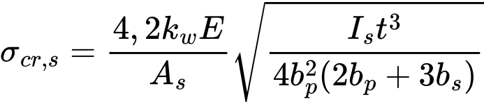
where: | bp | is the notional flat width of plane element shown in figure 5.11, |
bs | is the stiffener width, measured around the perimeter of the stiffener, see figure 5.11, | |
As, Is | are the cross-section area and the second moment of area of the stiffener cross-section according to figure 5.11, | |
kw | is a coefficient that allows for partial rotational restraint of the stiffened flange by the webs or other adjacent elements, see (5). For the calculation of the effective cross-section in axial compression the value kw = 1,0. |
For two symmetrically placed flange stiffeners, the elastic critical buckling stress σcr,s should be obtained from equation (5.23a):
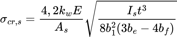
where: | be | = 2 bp,1 + bp,2 + 2 bs |
b1 | = 2 bp,1 + 0,5 br | |
bp,1 | is the notional flat width of an outer plane element, as shown in figure 5.11, | |
bp,2 | is the notional flat width of the central plane element, as shown in figure 5.11, | |
br | is the overall width of a stiffener, see figure 5.11, | |
As, Is | are the cross-section area and the second moment of area of the stiffener cross-section according to figure 5.11. |
For a multiple stiffened flange (three or more stiffeners), the elastic critical buckling stress σcr,s should be obtained from equation (5.23c):
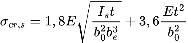
where: | Is | is the sum of the second moment of area of the stiffeners about the centroidal axis a-a, neglecting the thickness terms bt3/12, |
b0 | is the width of the flange as shown in figure 5.11, | |
be | is the developed width of the flange as shown in figure 5.11. |
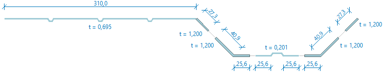
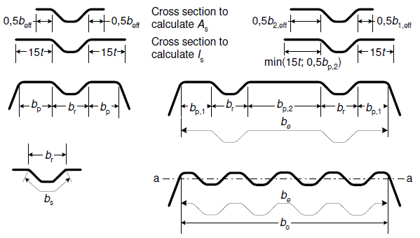 Figure 5.11: Compression flange with one, two or multiple stiffeners
Calculation of effective widths of webs
If the webs are at least partially compressed, the effective widths seff,1 to seff,n of the web plane elements are determined. The effective widths are calculated acc. to EN 1993-1-3, 5.5.3.4.3. The effective widths are summarized in figure 5.12.
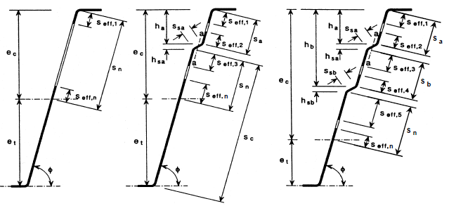 Figure 5.12: Effective cross-sections of webs of trapezoidal profiled sheets
Calculation of the critical stress on webs
The calculation of the critical stress on webs is carried out acc. to EN 1993-1-3, 5.5.3.4.3 (7), equation (5.39a):
![]()
where: | s1 | = 0,9 (sa + ssa + sc) for a single stiffener |
= sa + ssa + sb + 0,5 (ssb + sc) for web with two stiffeners | ||
s2 | = s1 - sa - 0,5 ssa | |
kf | is a coefficient that allows for partial rotational restraint of the stiffened web by the flanges assumed as 1,0 | |
Is | is the second moment of area of a stiffener cross-section comprising the fold width ssa and two adjacent strips, each of width seff,1, about its own centroidal axis parallel to the plane web elements | |
sc | as defined in Figure 5.12 |
Calculation of the modified elastic critical stress
In the case of sheeting with internal stiffeners both on the flanges and webs, a modified critical stress acc. to EN 1993-1-3, 5.5.3.4.4 (1), equation (5.42) is determined:
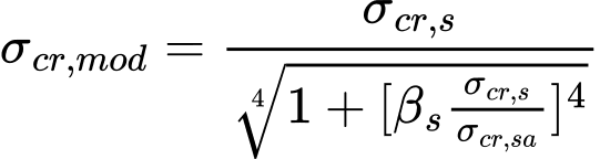
where: | σcr,s | is the elastic critical stress for an intermediate flange stiffener, |
σcr,sa | is the elastic critical stress for a single web stiffener, | |
As | is the effective cross-section area of an intermediate flange stiffener, | |
Asa | is the effective cross-section area of an intermediate web stiffener, | |
βs | = 1 - (ha + 0,5 hha) / ec for a profile in bending, | |
= 1 for a profile in axial compression. |
In case the profile contains stiffeners on the flanges only:
![]()
In case the profile contains stiffeners on the webs only:
![]()
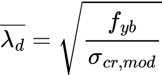
Calculation of the reduction factor χd for the distortional buckling resistance
Factor χd is determined acc. to EN 1993-1-3, 5.5.3.1 (7), equations (5.12a), (5.12b), (5.12c), (5.12d):
| if |
| |
| if |
| |
| if |
| |
|
Determination of the effective cross-section
The effective cross-section is created by reducing the gross cross-section by combining the following two ways:
- By introducing openings (holes) on the compression flanges and webs based on the calculated effective widths of the individual flat parts,
- By introduction of the thickness reductions on compression stiffeners and on adjacent flat parts. The thickness reduction is expressed using reduced thickness tred, acc. to EN 1993-1-3, 5.5.3.4.2 (8) and (11) and acc. to 5.5.3.4.3 (14):
![]()
An exception to the above are trapezoidal sheets with three or more stiffeners on the compression flange. In this case, the entire compression flange, including both flat parts and stiffeners, is reduced by introducing a reduced thickness only:
![]()
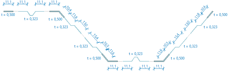
Examples of the effective cross-sections of trapezoidal sheets
- Example of compression effective cross-section with stiffeners on flanges and webs. There are reductions (holes) due to local buckling on flat parts, thickness reductions due to distortional buckling are applied to stiffeners and adjacent flat parts.
- Example of compression effective cross-section with multiple stiffened flange with three stiffeners. The entire flange, including both flat parts and stiffeners, is reduced by introducing a reduced thickness only.