Linear stability
The stability analysis provides important information regarding the behaviour of a structure. The main result is the proportion between applied load and critical load, which causes loss of structural stability. The buckling shape shows the mechanism of failure and can be used for estimation of character of geometric imperfections, that are decisive for the structure.
The problem of linear stability can be described as the problem of determining critical loads of ideal structure as the factor for the load, which really acts on this structure. For this purpose it is necessary to write the equilibrium conditions for the deformed structure and include the effect of axial forces on the lateral stiffness of members. Equilibrium equation can be described with the help of following expression:
![]()
Where is: | K |
|
Kσ |
| |
r |
|
Like the eigen shapes, the buckling form is also standardized, the standardized values of joint deformations are not displayed. The above equation is similar to equation describing the eigen shapes. Unlike eigenmodes, the stability problem is interested only in the lowest eigen number of the equations. This number is marked as λcrit. The vector R corresponds to the load distributed along the structure. Following expression may be used for determination of critical load:
![]()
This vector Rcrit corresponds to the critical load that causes the loss of stability of the whole structure. If the value of λcrit is negative, the structure is stable and loss of stability may occur only for load with opposite direction.
Subspace iteration method and Lanczos method
This equation is a general problem of eigenvalues. Both subspace iteration and Lanczos methods. Subspace iteration method was modified in order to solve the structures, which contain both tensile and compressive members. The Lanczos method is more conservative in this respect and requires that the initial stress matrix is positive definite. In other words, it allows to solve only the structure, which contain only unloaded members or members in compression. The advantages and disadvantages of both methods are described in detail in the previous chapter.
Inverse matrix method
One of the best-known methods, which is solely intended to find the lowest eigenvalue of an equation is the method of inverse iteration. As is already evident from the name is an inverse iteration method by iteration. This method is relatively reliable and accurate in the sense that repeating the iteration cycle increases the precision closer to the correct solution. Unfortunately, in some cases, the speed of convergence is very slow, and the maximum number of possible iterations, which is equal to 200, may not be always sufficient. Therefore, the results are supplemented with information about the achieved accuracy. In case that the convergence was not achieved, the user can either increase the number of iterations, or to reduce the required accuracy, or to select another method.
Recommendation
As the superposition principle can't be used in stability analysis, the calculation is performed only for the defined combinations. The results are characterized by a combination of critical load factor λcrit (marked as Fcrit) and its buckling shape. The value of λcrit should be greater than 4 for all combinations. Otherwise, the designer should seriously review the design concept and the static model, reformulate it or consider possible design modifications.
Following notes refer to the difference between spatial and planar structures. The user should respect that the planar structure loaded in a plane tends to deviate from the plane of the structure. If the deviation from the plane of the structure is prevented, the critical load factor λcrit is significantly higher. This fact is demonstrated on the example of a simple plane frame whose columns are loaded in the frame plane by axial forces. The result is shown in the following figure. First case shows out of plane buckling, the second one shows in plane buckling, as the out of plane buckling was prevented. The λcrit is four times greater.
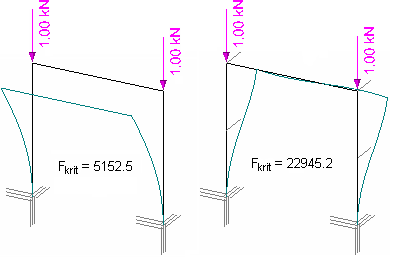 Buckling out of plane and in plane
The calculation of buckling lengths is a rather complicated issue and there is no general rule in this area. Users have to respect engineering experience and common sense. The stability analysis provides simple input for the estimation of buckling lengths. The following procedure may be used for significantly compressed members: In the first step, it is necessary to determine the axial forces in the structure. In the second step, it is possible to estimate the value λcrit and determine the axial forces corresponding to the critical load using formula
![]()
Where is: | N |
|
The buckling length can be calculated using the Euler expression:
![]()
Where is: | lh |
|
EI |
| |
Nkrit |
|
This formula was derived assuming axially loaded straight member. Its use for estimation of buckling lengths of generally loaded structures should therefore be subject to a thorough analysis, as the applicability of this formula should refer only to the significantly compressed members with the behaviour of a lone straight bar. This fact corresponds to the rod 3 on the following figure, while the rods 1 and 2 only substitute the flexible support of the upper joint of member 3 and their buckling verification is pointless. The rod 3 acts as a spring supported cantilever. Therefore, the calculation of buckling lengths of the rods 1 and 2 would be pointless.
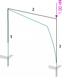 Axially loaded member