Shear reinforcement
This window contains properties of transverse reinforcement and performs verification of shear forces and torsional moments. Cross-sections without specified shear reinforcement are analysed as plain concrete members. Properties of shear reinforcement are placed in the upper part of the window. Following types of reinforcement are supported:
- Boundary stirrups - closed stirrups along the cross-sectional perimeter that are able to resist both shear forces and torsional moment (included only in certain programs)
- Ties, inner stirrups - inner parts of stirrups or ties between upper and bottom longitudinal reinforcement (may be specified in two directions in certain programs)
- Bent-up bars - shear reinforcement with angle between the reinforcement and the member axis in the interval <45,0;90,0>
Characteristics of individual reinforcement types:
Boundary stirrups
This reinforcement is considered as a basic transverse (shear) reinforcement of the member. Shape of bars respects the geometry of cross-section, distance from the edge is equal to the specified cover. The stirrups are specified by the bar diameter and spacing between bars along the member axis. Two profiles per bar are considered automatically.
Analysis of torsion can be influenced by the setting "Torsion". These options are available:
- Consider only to shear resistance - Complete bearing capacity of stirrups is considered in the analysis of shear. Stirrups aren't considered during the analysis of torsion. This option should be used for open stirrups without any torsional resistance.
- Split to shear and torsion automatically - Bearing capacity of stirrups is divided between analysis of shear and torsion in that way that both analysis provide the same utilization.
- Consider to torsion resistance with ratio - Bearing capacity of stirrups is divided between analysis of shear and torsion according to the specified ratio. Input value is the bearing capacity of stirrups for analysis of torsion.
Ties, inner stirrups
Inner bars of stirrups and ties can be specified in this part. The reinforcement is specified by the diameter, number of bars and spacing along the member axis. Spacing and diameter can be automatically copied from boundary stirrups using the setting "Same as boundary stirrups". This behaviour is suitable for reinforcement made of inner parts of boundary stirrups.
Bent-up bars
The difference between bent-up bars and inner stirrups is the angle between bar and member axis. Bent-up bars are specified by the diameter, number of bars, pitch and spacing along the member axis. Bent-up bars are considered to be placed only in one point of the member length (not in the row along the member length). For other cases, the setting "As row of bent-up bars" shall be switched on. Spacing of bent-up bars along the member length has to be specified in this case.
Inner lever arm
The user defined value of inner lever arm can be specified in this part. This value is one of the fundamental inputs for shear analysis. Available is automatic calculation (described in the theoretical part of help) or manual input as a portion of effective depth of cross-section d. The inner lever arm may be considered as 0,9d according to 6.2.3(1) of EN 1992-1-1 (provided that the member isn't loaded by normal force).
Angle of compression struts
Angle of compression struts can be calculated automatically by the software or specified manually by the user. Automatic iteration is based on finding the pitch for which the maximum shear VRd,max is equal to the bearing capacity of the shear reinforcement VRd,s. Permissible interval for the pitch is <21,8°;45°> according to 6.2.3(2) of EN 1992-1-1.
Information
Bottom part of the window shows both the results of the analysis (described in the chapter "Ultimate limit state - shear") and verification of structural rules (described in the chapter "Structural rules").
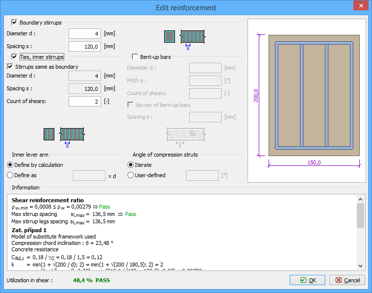 Window "Edit reinforcement"