Base plate in shear
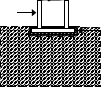
The shear forces between base plate and foundation aren't verified in the software. Shear forces may be transferred by:
|
|
|
|
|
|
|
|

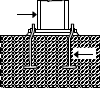

The value of friction factor is recommended as μ=0.4 (CEB, 1997), combined with the partial safety factor γ= 1,5. The friction may be increased due to pretension of bolts.
The anchoring bolts may be verified in accordance with (CEB, 1997). The interaction of bending and shear resistance of anchoring bolts is analysed in this case.
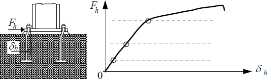 Deformation-force diagram of anchoring bolts in shear
The tensile failure appears after significant deformation (Weynand, 1999; Bowman 1989). The resistance may be calculated as reduced bolts resistance in tension, that is described in the same way as shear resistance:
![]()
Where is: | fub |
|
γmb |
|
The bolts 4.6 have α= 0,375, the bolts 5.6 have α= 0,250. This expression is verified for grouting thickness till 60mm (Bowman 1989). The shear resistance of bolts in foundation depends on the distance from base end and should be checked separately. Usually, bolts in tension and interaction of stresses are not considered.
References
CEB: Design of Fastenings in Concrete, Design guide, Thomas Telford Services Ltd, London 1997, s. 83, ISBN 0 7277 2558 0.
COST C1: Column Bases in Steel Building Frames, ed. K. Weynand, EC, Brussels 1999
Bowman L P, Gresnight A. M., Romeijn, A: Reserch into the connection of steel base plate to concrete foundation, holandsky, Stevin Laboratory Report No.: 25.6.89.05/c6, Delft 1989