End plate or column flange in bending, bolts in tension
Equivalent T-stub
Resistance and stiffness of column flange or end plate in bending is calculated with the help of equivalent T-stub with one row of bolts.
 Equivalent T-stub
Resistance
There are three collapse modes for equivalent T-stub:
- Complete yielding of the flange
- Bolt failure with yielding of the flange
- Bolt failure
Bolt resistance is based on the tensile resistance or stress under washer (or bolt head/nut):
![]()
Where the dimension dw is selected according to the size of washer or nut:
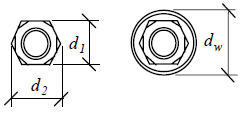 Dimensions of nuts and washers
The resistance of equivalent T-stub is calculated as a minimum resistance for three failure modes described above. The first failure mode (yielding of the flange) is given by the expression in accordance with table 6.2:
![]()
The more exact method is
![]()
Second failure mode is given by the formula
![]()
This expression is usef for the third failure mode:
![]()
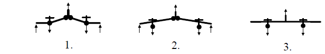 Failure modes
Where is:
![]()
![]()
![]()
![]()
The equivalent T-stub is selected in that way, that the bending about the beam web appears. Only exception are the bolts in unstiffened overhanging part of the plate. The bending is considered about the beam flange in this case.
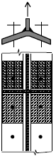 The equivalent T-stub for stiffened column web
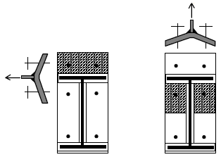 The equivalent T-stub for unstiffened overhanging part of the plate and fof bolts under the flange
The resistance of equivalent T-stub is calculated for both sides of the connection (column flange and end plate). The minimum value is considered as the resulting resistance.
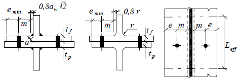 Dimensions of welded and rolled T-stub
Effect of axial stress in column
The connection resistance may be affected for combination of transverse bending and axial stress (due to axial force and bending moment). If the stress in the column flange σcom.Ed is greater than 180MPa (for S235), the resistance moment of the flange Mpl.Rd is reduced by the factor
![]()
The effective length of the equivalent T-stub
The effective length of the equivalent T-stub Leff is calculated for individual bolt rows using the method of plastic hinges. The worst value is considered when more failure modes may appear. As the second failure mode cannot appear for circular failure mode (length Leff.cp), two different effective lengths according to the figure below are used.
![]()
![]()
Circular failure | Other failure | ||
Leff.cp | Leff.op | ||
one bolt | bolts group | one bolt | bolts group |
|
|
|
|
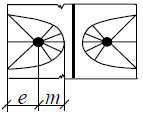
The effective length of the equivalent T-stub for circular failure is calculated as the length of one half of the T-stub, that has the same resistance as circular plate loaded in the middle and supported along its perimeter. The assumption m = r ≈ n was confirmed by tests. Therefore, the corresponding expression is
![]()
The effective length for bolts close to the plate edge is calculated in a similar way:
![]()
 Circular plastic hinge for bolts close to the plate edge
The effective length Leff for bolts along the stiffener of flange or column (and for bolts under the beam flange) is calculated separately using following expression
![]()
The effective length for the failure of bolts group is calculated according to the following formula
![]()
The factor α is determined from the graph, that is based on analytical and numerical methods used for verification of the bolt in the corner. Following parameters are used:
![]()
The dimensions m, m2 and e of T-stub are shown in the following figure:
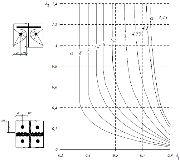 Graph for calculation of effective length close to the stiffener
The values of the factor α are in the interval between 4,45 and 8 depending on the bolt position in the corner. These values were found with the help of tests and analytical methods.
 Plastic hinges at the end of flange
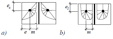
The effective length for bolts at the end of the flange (option a in the figure above) is calculated using expression
![]()
The effective length for circular failure (option b in the figure above) is calculated using expression
![]()
The effective length for bolts between two stiffeners (option a in the figure below) is calculated using expression
![]()
Where αR corresponds to mR and αL is calculated for mL.
The effective length for bolts between stiffener and end of flange (option b in the figure below) is calculated using expression
![]()
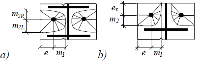 Plastic hinges between two stiffeners and between stiffener and flange
One of following failure modes is the decisive one for bolts at the end of plate:
- Plastic circular failure
![]()
- Failure of individual bolts
![]()
- Failure in the corner of the plate
![]()
- Failure of the bolts group
![]()
- Bending of plate
![]()
 Effective lengths at the end of plate
The resistance of individual rows of bolts is calculated according to the following table for flanges of unstiffened columns:
Rows of bolts | Failure of single row | Failure of rows group | ||
circular (Leff.cp) | other (Leff.op) | circular (Leff.cp) | other (Leff.op) | |
Internal | 2πm | 4m+1,25e | 2p | p |
End | 2πm πm+2e1 | 4m+1,25e 2m+0,625e+e1 | πm+p 2e1+p | 2m+0,625e+0,5p e1+0,5p |
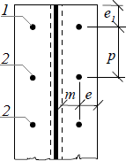 Unstiffened column flange: End (1) and internal (2) rows
The resistance of individual rows of bolts is calculated according to the following table for flanges of stiffened columns:
Rows of bolts | Failure of single row | Failure of rows group | ||
circular (Leff.cp) | other (Leff.op) | circular (Leff.cp) | other (Leff.op) | |
Close to stiffener | 2πm | αm | πm+p | 0,5p+αm-2m-0,625e |
Internal | 2πm | 4m+1,25e | 2p | p |
End | 2πm | 4m+1,25e | πm+p | 2m+0,625e+0,5p |
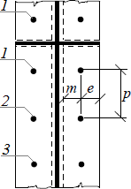 Stiffened column flange: row close to stiffener (1), internal (2) and end (3) rows
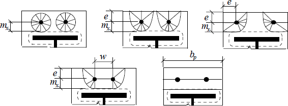
The resistance of individual rows of bolts is calculated according to the following table for end plates:
Rows of bolts | Failure of single row | Failure of rows group | ||
circular (Leff.cp) | other (Leff.op) | circular (Leff.cp) | other (Leff.op) | |
Out of flange in tension | 2πm πmx+w πmx+2e | 4mx+1,25ex e+4mx+0,625ex 0,5bp 0,5w+2mx+0,625ex | ||
Under flange in tension | 2πm | αm | πm+p | 0,5p+αm-2m-0,625e |
Internal | 2πm | 4m+1,25e | 2p | p |
End | 2πm | 4m+1,25e | πm+p | 2m+0,625e+0,5p |
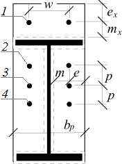 End plate: Rows out of flange in tension (1), under flange in tension (2), internal (3) and end (4) rows
The column flange may be restrained by backing plates:
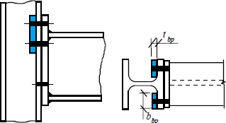 Backing plates (highlighted by blue)
Backing plates increase the resistance in the failure 1 (4 plastic hinges in T-stub). The increase is equal to the bending resistance of backing plate
![]()
Where the plastic moment is calculated using formula
![]()
Where is: | tbp |
|
fy.bp |
|
Resistance of unstiffened column flange in the welded joint
The resistance of unstiffened column flange in the welded joint is calculated using formula
![]()
but
![]()
Where is: | twc, tfc |
|
ffb, tfb |
|
Ans s= rc for rolled sections and s= ab.wf20,5 for welded sections. The factor k is calculated using formula
![]()
Stiffness
The assumption is that the stiffness of any component can be calculated separately. This assumption does not work for prying of bolts. In these cases, the stiffness depends also on the stiffness of T-stub. Only rough estimation is done in this case. The deformation of single row δb can be calculated uding formula
![]()
The stiffness of one row kb can be calculated using expression
![]()
The stiffness factor of plate in bending, where no prying occurs, is based on the expression for cantlever deformation:
![]()

EN 1993-1-8 uses initial spring value of T-stub length, that is estimated as Leff.ini= 0,9 Leff.
The stiffness factor calculation of T-stub with prying is more complicated, as mutual influence of bolts in tension and T-stub occurs. This effect is not considered and following expression is used (subscripts k4,5,6 correspond to the components according to EN 1993-1-8)
![]()
The backing plates do not increase the stiffness of T-stub significantly. Therefore backing plates are not considered in the calculation of stiffness.