Cracks
This part of the beam design shows results of crack calculation (serviceability limit state). The width of cracks along the whole member length is calculated and compared with the maximum value according to the standard or according to the user's input. The verification is performed only for load combinations "Quasi-permanent (SLS)".
The maximum crack width is considered in accordance with table 7.1N. Option for user defined value is also included. Setting "Calculate crack width only at upper/bottom edge" switches off the crack control on the cross-section sides. This setting is suitable for the verification of part of the structure (for example one linear meter of slab). Complete results can be displayed in a new window after using the button "In detail". The workspace is able to show diagrams of bending moments and crack width. Displayed quantities can be switched on/off in the window "Drawing settings", that can be launched using the button "Diagrams". The results for envelope of all relevant load combinations are displayed as a default. Results for certain load combination can be displayed with the help of drop-down menu in the heading of input frame.
Cracks may also arise from other causes such as plastic shrinkage or expansive chemical reactions within the hardened concrete (creeping). These factors are taken into account with the help of creep coefficient. The value of this coefficient can be changed in the window "Creep" that can be launched by the button "Creep coefficient".
Calculation and verification of cracks are described in the chapter "Serviceability limit state" of the theoretical help.
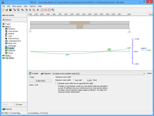 Part "Cracks" of member design