User interface in Fin 2D and Fin 3D
These changes in user interface were made:
Simplification of the tree menu
- Choice of active load case was moved to the heading of workspace. The new position corresponds to the selection of results in postprocessor.
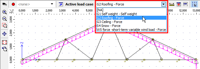 Choice of active load case
The selection of active load case was also added into the input frame in the mode "Topology" of the tree menu.
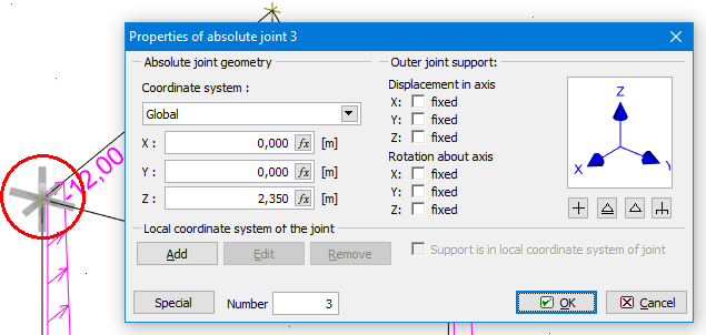
- Modes "Edit" and "Delete" can be used both for a work with joints and members. The edited element is highlighted by grey colour in the workspace.
 Highlighted joint in the workspace
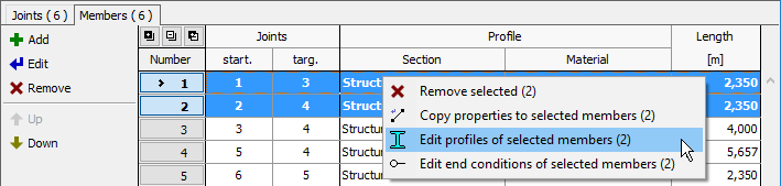
- The commands for the work with selected items (copy properties, edit supports, add loads etc.) are located only in the context menu, that can be opened on the workspace with the help of right mouse button. These tools are available only in cases when some elements are selected (highlighted by green colour in the workspace).
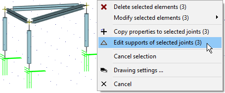 Context menu for selected joints
- Tools "Add scissor joint", "Convert joint to absolute" and "Divide members" were moved to the mode "Tools" of the tree menu. Alternatively, they are located in context menus for joints and members in the workspace.
- Tables of joint and members are organized into tabs in the bottom frame for the mode "Topology". Identical solution is used also for tables of joint and member loads and for several types of combinations in the mode "Load".
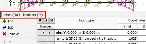 Tabs with joints and members tables
- Preprocessor and postprocessor were merged into one tree menu
- Design members are sorted into tabs according to the type of material in the part "Design".
Easy edit of joints and members
Any member or joint can be edit by double-click on the element in the workspace. This procedure opens corresponding editing window.
Work with selections
Selection of objects was modified according to the rules used in CAD applications. The selection is done by rectangular area. Dragging from left to right selects objects that are entirely enclosed in rectangle, dragging from right to left selects objects that are crossed by rectangle (the rectangle is drawn by dashed line in this case). The selection can be cancelled completely with the help of the key "Esc" or by the command "Cancel selection" in the context menu on the workspace. Certain objects can be removed from the selection by repeated selection with pressed key "Shift".
 Difference in the dragging from left to right (left figure) and from right to left (right figure)
The behaviour may be changed with the help of the setting "Use Shift to add to selection", which is located in the tab "General" of the window "Options". If checked, any new selection cancels previous selection. Adding of new objects to the existing selection can be performed with pressed key "Shift".
Also selection in tables was improved. Following shortcuts can be used:
- "Ctrl"+"A" - Selects all items in table
- Selection of range using "Shift" - Range (more following items) can be selected by clicking on the first and last item. When clicking on the last one, the key "Shift" has to be pressed.
- Addition of items to selection using "Ctrl" - Items can be added to existing selection with pressed key "Ctrl".
Right mouse button click on the selected items in the table opens context menu with tools for the work with selected items.
 Context menu for selected members in the table
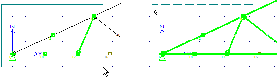
Simplified input of joints
Both absolute and relative joints can be inserted using the same tool "Add joint". The joint entered on the existing member is automatically recognized as relative one. Otherwise, it is entered as an absolute one. Both types use the supporting method given in the prototype of joint.
The relative joint can be inserted into the location given by the clicking or the position can be specified parametrically. The setting "Relative joint according to the prototype" has to be selected in the prototype properties in these cases.
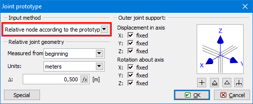 Choice of input method for relative joints
Graphical input in the program Fin 3D
The program "Fin 3D" features a new method of graphical input, that corresponds methods common in CAD applications. The range of functions is identical to existing graphical input in the program "Fin 2D". It is possible to use snap points and snapping to significant directions.
 Snap points on a member
Settings for snap points and snapping to directions are located above the input fields in the bottom part of the tree menu.
 Settings for object snapping
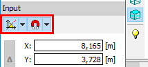
These input fields can be used both for the input of joints and members. It is possible to jump into input fields with the help of cursor or by keyboard entries "x", "y" and "z". For example, the expression x0y2z1.3 fills 0 into the input line "x", 2 into the input line "y" and 1.3 into the field "z".
 Input fields in the tree menu
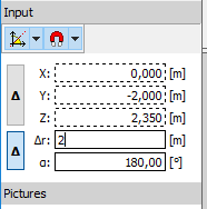
The easiest way of entering end point of a member is to specify the member direction by cursor and specify the length on keyboard. The length will be automatically filled into the field "Δr". The input has to be confirmed by the key "Enter". The program automatically snaps the cursor into directions 45°. This behaviour may be changed (switch off or change it to 30°) using the button "![]() ".
".
 Definition of member direction by the cursor and input of member length with the help of keyboard
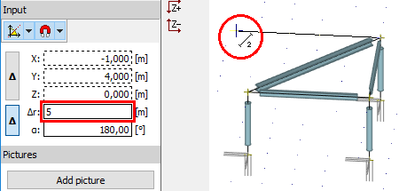
Alternatively, it is possible to use extended options of input fields in tree menu. Input fields "X" "Y" and "Z" are usable for the definition of the end point with the help of global coordinates, fields "r" and "α" define the end point by the member length and rotation about the axis y. Buttons "Δ" changes whether the input is considered in the global coordinate system or relatively to the beginning of the member. It is possible to jump into input fields with the help of cursor or by keyboard entries "x", "y", "z", "r" or "a". For example, the expression "r2a15" fills 2m into the field "r" and 15° into the field "α".